Sensors
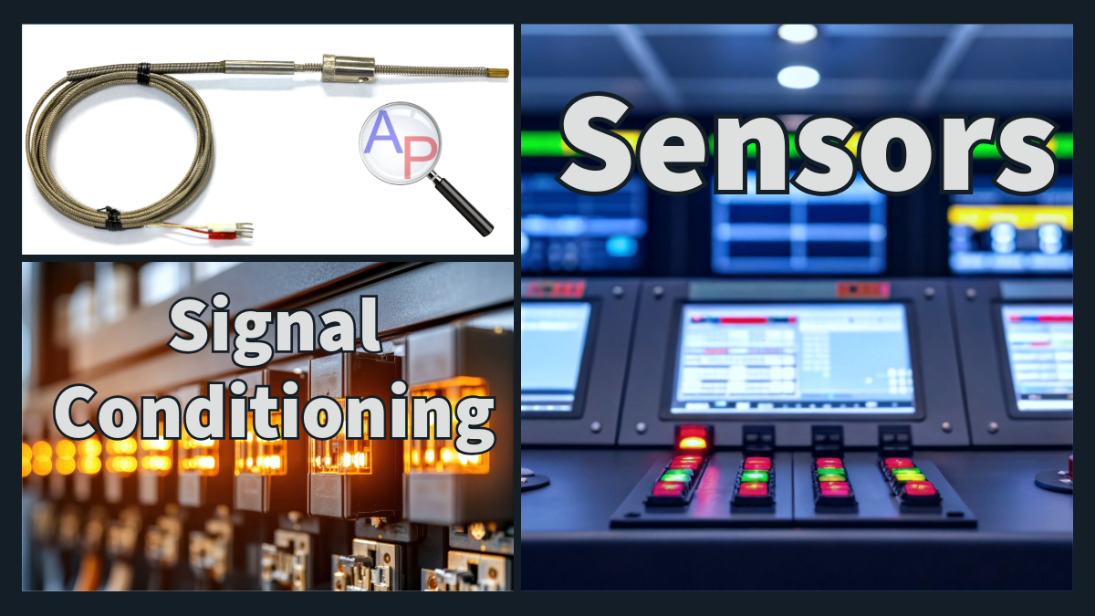


Sensors are the essential link between the physical world and electrical systems. They detect quantities such as pressure, flow, temperature, vibration, pH and composition and convert those quantities into electrical signals. These signals can be conditioned, transmitted and digitized for use in feedback control, data acquisition and optimization. Robust measurement is the foundation of industrial automation, Internet‑of‑Things devices and process control, and this page introduces common sensor technologies, signal standards and the integration into SCADA systems.
Physical to Electrical Transduction
Sensors employ different transduction mechanisms to translate a physical change into an electrical signal:
Resistive sensors: strain gauges and pressure diaphragms change resistance with deformation and resistance temperature detectors (RTDs) and thermistors change resistance with temperature. A Wheatstone bridge converts the resistance change into a millivolt output.
Capacitive sensors: distance or pressure change the separation between capacitor plates, causing a change in capacitance and therefore a change in voltage when the sensor is driven with an AC excitation.
Inductive and magnetic sensors: linear variable differential transformers (LVDTs) and Hall‑effect sensors change inductance or magnetic flux with position or current. The resulting voltage is proportional to displacement, velocity or magnetic field.
Piezoelectric sensors: mechanical stress on a piezoelectric crystal generates a charge. Acceleration and vibration sensors use charge amplifiers to convert this charge into a voltage.
Electrochemical and optical sensors: pH electrodes generate a potential difference across a glass membrane that depends on hydrogen ion concentration. Gas composition analyzers measure absorption of infrared or ultraviolet light and produce a corresponding current.
Frequency‑output sensors: turbine flow meters produce pulses with frequency proportional to flow rate. Ultrasonic distance sensors measure the time of flight of a pulse reflected from a target.
These primary signals may be very small (often microvolts or millivolts) and susceptible to noise. Before they can be transmitted or digitized they must be conditioned.
Signal Conditioning
Amplification and filtering: instrumentation amplifiers boost low‑level signals and reject common‑mode noise. Low‑pass filters remove high‑frequency noise while preserving the measurement bandwidth.
Linearization and temperature compensation: many sensors have a nonlinear response or drift with temperature. Signal conditioners include lookup tables, polynomial approximations or cold‑junction compensation (for thermocouples) to correct these effects.
Isolation and safety: galvanic or optical isolation prevents ground loops and protects both sensor and controller. Safety barriers are used in hazardous areas.
Standardization: scaling circuits convert the conditioned signal into standardized ranges such as 0-10 V, 1-5 V or 4-20 mA so that any controller or SCADA module can interpret it. Pneumatic transmitters use 3-15 psig for compatibility with legacy systems and fail‑safe operation.
Case Study: Type‑K Thermocouple
A Type‑K thermocouple produces a small voltage proportional to the temperature difference between the sensing junction and a reference. Over a 0-1000 °C range the output is approximately 0-50 mV. A signal conditioner must amplify this millivolt signal, apply cold‑junction compensation and scale it to a standard output. For a 4-20 mA loop the relationship between temperature `T`, in °C, and current `I_{out}`, in mA, is (for example)
$$I_{out} = 4 \text{mA} + \frac{16 \text{mA}}{1000 \text{°C}} T$$
so that `I_{out}=4 \text{ mA}` at 0 °C and `I_{out}=20 \text{ mA}` at 1000 °C. The conditioner includes an instrumentation amplifier with a gain of about 300, a precision reference and cold‑junction sensor. For microcontroller integration the same thermocouple may be connected to an integrated converter such as the MAX6675, which digitizes the temperature directly and communicates via an SPI bus.
Industrial Signal Standards
The most common standards for transmitting sensor signals in process control are summarized below. The 4-20 mA current loop dominates because the current is immune to voltage drops along long cables and 0 mA indicates a broken loop.
Common Instrumentation Signal Types
| Signal | Description | Comments |
|---|---|---|
| 4-20 mA current loop | Current proportional to measurement. 4 mA represents zero and 20 mA represents full scale. | Immune to voltage drop, can power two-wire transmitters. 0 mA denotes fault. |
| 0-10 V or 1-5 V | Voltage proportional to measurement. | Simple to implement. Susceptible to noise and voltage drop over long runs. |
| 3-15 psig | Pneumatic pressure used in legacy systems. | Useful in hazardous areas. Provides fail-safe operation on loss of supply. |
| Pulse/frequency | Pulses per second proportional to measurement (e.g., turbine flow meters). | Digital nature improves noise immunity. Frequency easily counted. |
| Digital fieldbus | Protocols such as HART, Modbus, Profibus, Foundation Fieldbus provide bidirectional communication. | Allow multiple sensors on one pair of wires. Send diagnostics in addition to process variable. |
| Wireless | ISA100, WirelessHART, Wi-Fi and Bluetooth for remote sensors. | Suitable for mobile or difficult-to-wire equipment. Limited bandwidth and power. |
Analog signals provide a continuous representation of the process variable, while digital signals encode the measurement as discrete numbers. Digital sensors often include the transducer, signal conditioner and analog‑to‑digital converter in one housing. This integration improves accuracy and reduces wiring complexity.
Microcontroller and IoT Sensors
Educational and IoT platforms such as Arduino and ESP32 read sensor signals with built‑in analog‑to‑digital converters (ADCs) or digital communication ports. These boards typically operate at 3.3 V or 5 V logic levels and interface with inexpensive sensors. The following table lists common microcontroller signal types and examples:
Sensor Signal Types and Interfaces
| Signal type | Interface / Range | Example sensors |
|---|---|---|
| Analog voltage | 0-1 V, 0-3.3 V or 0-5 V read with the microcontroller’s ADC. | Potentiometers, LM35 temperature sensor (10 mV/°C), photoresistors, strain gauges with op-amp. |
| Pulse-width or frequency | Time of flight, duty cycle or frequency measured by digital timing. | HC-SR04 ultrasonic distance sensor, anemometers, turbine flow meters. |
| I²C digital bus | Two-wire serial bus with addressable devices. | BMP280 pressure sensor, BME280 humidity/temperature/pressure, SCD30 CO₂ sensor. |
| SPI digital bus | Four-wire full-duplex bus and higher speed than I²C. | MAX6675 thermocouple converter, VL53L0X time-of-flight distance sensor. |
| UART / 1-Wire | Serial or single-wire protocols. | DS18B20 digital thermometer, GPS modules, pH sensors with serial output. |
On a microcontroller the raw sensor signal is often scaled with a resistor divider or operational amplifier to fit within the ADC range. Many breakout boards integrate the signal conditioning and present a digital interface so that no external circuitry is required.
Applications in Industrial Processes
Electrorefining: Copper electrorefining tankhouses use sensors to monitor electrolyte temperature, cell voltage and copper concentration. Temperature sensors (thermocouples or RTDs) ensure the electrolyte is kept within an optimal range to maximize current efficiency and cathode purity. Voltage sensors detect shorts between anodes and cathodes and help identify cells requiring maintenance. Inline analyzers measure copper concentration and transmit results via 4-20 mA loops or digital fieldbus to the SCADA system. Real‑time data allow operators to adjust current, flow and reagent addition to maintain quality and safety.
Bioprocesses in pharmaceutical manufacturing: Bioreactors rely on precise control of pH, dissolved oxygen, temperature and pressure. Glass‑electrode pH probes generate a millivolt signal that varies approximately −59 mV per pH unit at 25 °C. This weak signal is amplified by a high‑impedance preamplifier and conditioned to 4-20 mA or digital HART output. Optical or electrochemical dissolved‑oxygen sensors may provide a direct 4-20 mA output or communicate via a digital protocol. Temperature is monitored with RTDs or thermocouples. Pressure sensors track overpressure to ensure safety. Single‑use sensors and wireless adapters are increasingly used to avoid contamination and to simplify set‑up.
Polymer production: Polymerization reactors are highly exothermic, requiring accurate temperature and pressure sensing to avoid runaway reactions. Resistance temperature detectors measure reactor temperature, while pressure transducers monitor vessel pressure. Viscosity can be inferred from torque measurements on agitators or from online rheometers. These instruments output either a voltage or current proportional to viscosity. Gas composition analyzers measure monomer concentration and solvent composition to control feed rates. Sensors in polymer production must often withstand high temperatures and corrosive chemicals, so their housings and diaphragms are made from materials such as stainless steel or PTFE. Signal conditioners provide isolation and scale the outputs to standard ranges for the distributed control system.
Summary of Physical Quantities and Typical Outputs
Quantities, Measurement Principles, and Conditioned Signals
| Quantity & sensor | Measurement principle | Typical conditioned signal |
|---|---|---|
| Pressure (strain gauge) | Wheatstone bridge converts strain to mV. | 1-5 V, 4-20 mA or 0-100 mV (microcontroller). |
| Flow (orifice plate/turbine) | Differential pressure or pulse frequency proportional to flow. | 4-20 mA, 0-10 V, frequency pulses. |
| Temperature (thermocouple, RTD) | Thermocouple produces mV per °C and RTD changes resistance. | 4-20 mA, 0-5 V, SPI or I²C digital. |
| Vibration/acceleration (piezoelectric) | Stress on crystal generates charge. | ±5 V after charge amplifier or digital I²C. |
| pH (glass electrode) | Nernst potential across membrane ≈ −59 mV per pH unit. | −414 to +414 mV raw and conditioned to 4-20 mA or Modbus. |
| Composition (infrared/chemical) | Absorption or electrochemical reaction proportional to concentration. | 0-10 V, 4-20 mA, digital (HART, Ethernet). |
These examples illustrate how diverse sensors translate a wide range of physical phenomena into standardized electrical forms. Signal conditioning bridges the gap between delicate sensor outputs and robust transmission formats used by industrial controllers and SCADA systems. When coupled with actuators and control algorithms, sensors enable the closed‑loop control that underpins modern manufacturing and data‑driven engineering.
Quiz: Sensor Calibration & Signals
Test your understanding with the following questions. Click "Select" to reveal the answer.
1. A 4-20 mA temperature transmitter is ranged 0-200 °C. What output current corresponds to a measured temperature of 50 °C?
Incorrect. Use the linear relationship between temperature and current. 0 °C corresponds to 4 mA and 200 °C to 20 mA. Determine the fraction of span and add it to 4 mA.
Incorrect. Check the calculation again.
Correct. The output is `I = 4\text{mA} + 16\text{mA} \times (50/200) = 4 + 4 = 8.8\text{mA}`. At 50 °C the transmitter outputs 8.8 mA.
Incorrect. This current corresponds to a higher temperature. Calculate the correct value.
2. A turbine flow meter produces 100 pulses per second at full scale. If 40 pulses per second are measured, what fraction of the full flow is present?
Incorrect. The frequency is proportional to the flow rate. Determine the ratio of the measured frequency to the full‑scale frequency.
Correct. 40 pulses per second is 40 % of the full‑scale frequency (100 Hz), so the flow is 40 % of the maximum.
Incorrect. The measured frequency is lower than the full‑scale value.
Incorrect. Recalculate the fraction.
3. A 0-10 V level transmitter is ranged 0-5 m. What output voltage corresponds to a measured level of 2 m?
Incorrect. The transmitter output is linear with level. Determine the fraction of the span (2 m/5 m) and multiply by 10 V.
Correct. The measured level is 40 % of the range (2/5). Multiply 40 % by the 10 V span: 0.4 × 10 V = 4.0 V.
Incorrect. 5.0 V would correspond to 2.5 m, not 2 m.
Incorrect. This voltage corresponds to a higher level. Calculate the correct value using the linear relationship.
4. Which of the following is a digital communication protocol commonly used by sensors to transmit data?
Incorrect. The 4-20 mA loop is an analog current signal standard, not a digital communication protocol.
Incorrect. This is an analog voltage range. Digital protocols transmit data in discrete bits.
Correct. Modbus is a digital fieldbus protocol that allows bidirectional communication between sensors and controllers.
Incorrect. A Wheatstone bridge is a resistive circuit used to measure small changes in resistance, not a communication protocol.
5. A platinum RTD has 100 Ω at 0 °C and 138.5 Ω at 100 °C (assume linear). If the measured resistance is 119 Ω, what is the approximate temperature?
Incorrect. Use the linear relationship: temperature = (measured - 100 Ω)/(138.5 Ω - 100 Ω) × 100 °C. Check your calculation.
Correct. The resistance difference from 0 °C is 19 Ω. Divide by the 38.5 Ω span: 19/38.5 ≈ 0.49, giving ≈ 49 °C.
Incorrect. This resistance is lower than that corresponding to 65 °C. Recalculate using the given linear relation.
Incorrect. The measured resistance is closer to the midpoint between 100 Ω and 138.5 Ω, which corresponds to around 50 °C, not 75 °C.
Exercise 1 (20 min): Bioprocess pH Transmitter Calibration
A bioreactor uses a glass‑electrode pH probe with a Nernst slope of approximately −59 mV per pH unit at 25 °C. A transmitter ranges the pH from 4 to 10 and converts it to a 4-20 mA signal. Assume the reference electrode potential is 0 mV at pH 7.
Tasks:
- What electrode potential (in mV) is expected at pH 4 and at pH 10?
- For the 4-20 mA transmitter, calculate the output current at pH 5.
- If the transmitter output is 12 mA, what is the measured pH?
- Explain why temperature compensation is necessary for accurate pH measurement with a glass electrode.
Solution
- The electrode potential relative to pH 7 is given by `E = -59\text{ mV}\times(\text{pH}-7)`. At pH 4: `E=-59\times(4-7)=+177\text{ mV}`; at pH 10: `E=-59\times(10-7)=-177\text{ mV}`. Do not mistakenly reverse the sign. Note that the potential is positive at lower pH and negative at higher pH.
- The transmitter maps pH 4 to 4 mA and pH 10 to 20 mA. At pH 5 the fraction of span is `(5-4)/(10-4)=1/6`. The output is `I_{\text{out}} = 4\text{ mA} + 16\text{ mA}\times\frac{1}{6} \approx 4 + 2.67 = 6.67\text{ mA}`. A common mistake is to divide by 10 instead of the 6‑unit pH span.
- Rearranging the linear relationship `I_{\text{out}}=4 + 16(\text{pH}-4)/6` gives `\text{pH} = 4 + \frac{I_{\text{out}}-4}{16}\times6`. For `I_{\text{out}}=12\text{ mA}`, `(12-4)/16=0.5`, so `\text{pH}=4+0.5\times6=7`. 12 mA corresponds to neutral pH.
- The Nernst slope (−59 mV per pH unit) depends on temperature (-59mV @25 °C and −65 mV at 37 °C). If temperature changes, the pH electrode output per unit pH changes. Transmitters include temperature compensation to correct the slope and reference potential, otherwise the measured pH drifts with temperature.
Exercise 2 (20 min): Polymer Reactor Sensor Scaling
A polymerization reactor is instrumented with a pressure transmitter, a temperature transmitter, and a torque transducer to infer viscosity.
Tasks:
- The pressure transmitter ranges 0-20 bar and outputs 4-20 mA. What current corresponds to a measured pressure of 8 bar?
- The temperature transmitter uses an RTD and scales 50-250 °C to 1-5 V. If the reactor temperature is 150 °C, what is the transmitter output voltage?
- A torque sensor outputs 0-10 V for viscosities from 0-2000 cP. What viscosity does a reading of 7.5 V indicate?
- Give two reasons why a 4-20 mA loop is preferred over a 0-10 V signal for pressure measurement in a high‑temperature polymer plant.
Solution
- The span is 20 bar and the current spans 16 mA. Fraction of span: `8/20=0.4`. The output current is `I_{\text{out}}=4\text{ mA}+0.4\times16\text{ mA}=4+6.4=10.4\text{ mA}`.
- The temperature range is 200 °C (50-250 °C) and the voltage span is 4 V (1-5 V). At 150 °C the fraction of span is {(150-50)/200=0.5}. The output is `V_{\text{out}}=1\text{ V}+0.5\times4\text{ V}=3\text{ V}`.
- The torque transducer output is linear: viscosity `= (V_{\text{out}}/10\text{ V})\times2000\text{ cP}`. For 7.5 V: `(7.5/10)\times2000 = 1500\text{ cP}`.
- Current loops are less susceptible to voltage drop and electrical noise over long cable runs than voltage signals. They can power two‑wire transmitters so only one pair of wires is needed. In a polymer plant with high temperatures and electromagnetic interference from heaters and agitators, the 4-20 mA loop ensures a reliable signal and allows detection of open‑circuit faults (0 mA).
Exercise 3 (20 min): Electrorefining Measurement Loop
In a copper electrorefining tankhouse, sensors monitor copper concentration, electrolyte temperature, and cell voltage. A temperature sensor uses a thermocouple connected to an instrumentation amplifier. All instruments transmit on 4-20 mA loops powered from 24 V supplies.
Tasks:
- A copper concentration analyzer outputs 4-20 mA for concentrations from 0 to 60 g/L. If the loop current is 7.2 mA, what is the copper concentration?
- A type‑K thermocouple produces 40 µV per °C. It is connected to an instrumentation amplifier with a gain of 300. The cold‑junction (reference) is at 25 °C. What is the amplifier output voltage when the process temperature is 55 °C?
- The thermocouple transmitter operates from the 4-20 mA loop and requires at least 10 V to function. With a 24 V supply and maximum loop current of 20 mA, what is the maximum allowable load resistance?
Solution
- Remove the 4 mA offset and scale the remaining current: `I_{\text{span}}=7.2\text{ mA}-4\text{ mA}=3.2\text{ mA}`. The fraction of the 16 mA span is `3.2/16=0.2`. The concentration is `0 + 0.2\times60 = 12\text{g/L}`. A common mistake is to divide by the full 20 mA instead of the 16 mA span.
- The temperature difference is `ΔT=55-25=30\text{ ° C}`. The thermocouple voltage is `V_{\text{tc}}=40\text{ µV / °C}\times30\text{ °C}=1.2\text{ mV}`. The amplifier output is `V_{\text{out}}=300\times1.2\text{ mV}=360\text{ mV}`, or 0.36 V. Many confuse microvolts and millivolts. Always convert units before multiplying by gain.
- The loop supply is 24 V and the transmitter needs 10 V. The remaining 14 V appears across the load. At 20 mA the maximum load resistance is `R_{\text{max}} = \frac{14\text{ V}}{0.02\text{ A}} = 700\text{ Ω}`.