MicroPython Data Acquisition


Sensors take measurements of the physical environment such as pressure, temperature, position, distance, and sound. These measurements are the basis for most data-driven engineering applications. Raw measurements often require cleansing (filtering) to remove bad samples such as outliers, noise, or drift. Microcontrollers and microprocessors facilitate the collection and processing of data locally to the device. For example, a self-driving car may collect 25 GB/hr of data to enable self driving capabilities. Airplane jet engine collects approximately 50,000 GB/hr of data to monitor the health of the engine and detect early warning signs. Embedded systems use microcontrollers to collect the data and microprocessors analyze the data to extract valuable insights and recommend corrective actions. Cloud computing performs the analysis after the data is transferred to an online repository. Edge computing is a growing focus area to perform most of the calculations locally and send summary information to online repositories.
MicroPython / µPython
Most microcontrollers run custom build C code or similar lower-level programming languages build for limited resources. MicroPython can run on more capable microcontrollers (Arduino, ESP32, Teensy, Raspberry Pi Pico, and others). MicroPython is valuable for quick prototyping and reduced programming complexity. CircuitPython (from AdaFruit) is similar to MicroPython, but with an objective to be compatible with CPython. The community for MicroPython is larger with more supported boards.
Load Firmware
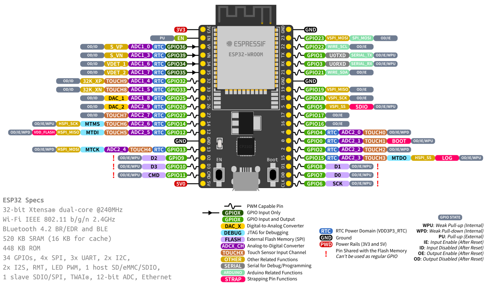
The example in this tutorial is with an Espressif ESP32 board.
Get started by loading either:
on the ESP32 microcontroller.
Method 1: MicroPython IDE
The easiest method is to use Thonny to load the firmware. Thonny is a Python Integrated Development Environment (IDE) for beginners and simplifies the process of running MicroPython code on a microcontroller. Thonny is a graphical interface that runs the esptool.py program for loading firmware. Open Thonny and select Tools...Options.
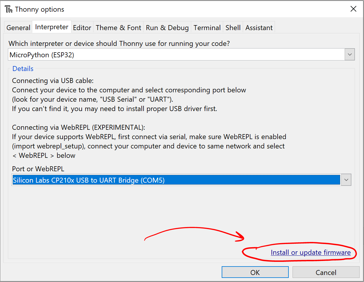
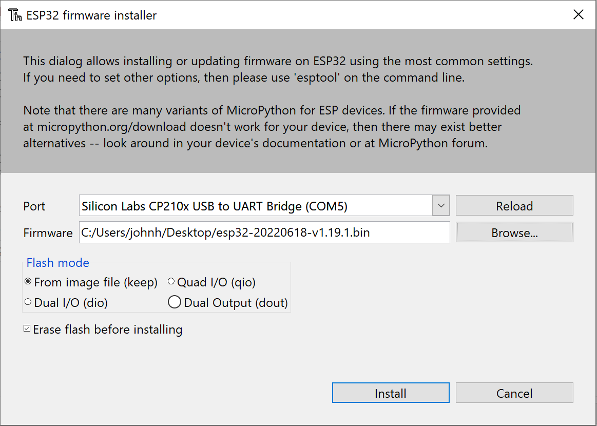
Select the correct port. The CP210x USB to UART Bridge VCP Driver may be required to communicate with the device over the USB connection. Also download and select the latest ESP32 WROOM or ESP32 S2 WROVER firmware file. Press the Boot button on the ESP32 to enter a write mode for the flash memory.
Method 2: Command Terminal with esptool
The MicroPython documentation has instructions for loading the firmware with esptool.py.
Run the esptool command from the command terminal. For Windows, search in the Device Manager for the correct COM port.
For Linux and MacOS, search for a USB connected device such as /dev/ttyUSB0.
Press the Boot button (bottom right corner) to enter a mode that allows the flash memory to be modified. Otherwise, there is an error such as "A fatal error occurred: Failed to connect to ESP32: Wrong boot mode detected (0x13)! The chip needs to be in download mode." See additional troubleshooting steps, if needed.
Next, run the command to load the firmware. Replace firmware.bin with the correct firmware name and the port COM5 with the correct port (such as /dev/ttyUSB0 for Linux).
Run Applications with Thonny
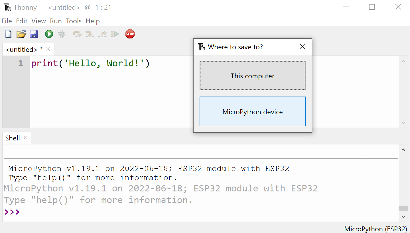
Stop and restart the Thonny interpreter to verify that the firmware is installed correctly. Enter print('Hello, World!') in the text editor and save and run the program on the ESP32 MicroPython Device as hello.py.
The boot.py script runs whenever the ESP32 turns on, followed by main.py. Do not overwrite these files or the ESP32 could become non-responsive to commands and require a reflash of the firmware.
Next, run a program that blinks the ESP32 LED indefinitely. Save the file as blink.py.
from machine import Pin
led=Pin(2,Pin.OUT)
while True:
led.on()
time.sleep(0.5)
led.off()
time.sleep(0.5)
Press the RST Reset button on the ESP32 to stop the program.
Run Applications with Arduino Lab
Once the firmware is loaded, Arduino Lab for MicroPython can also be used to run the code. First, connect to the port:
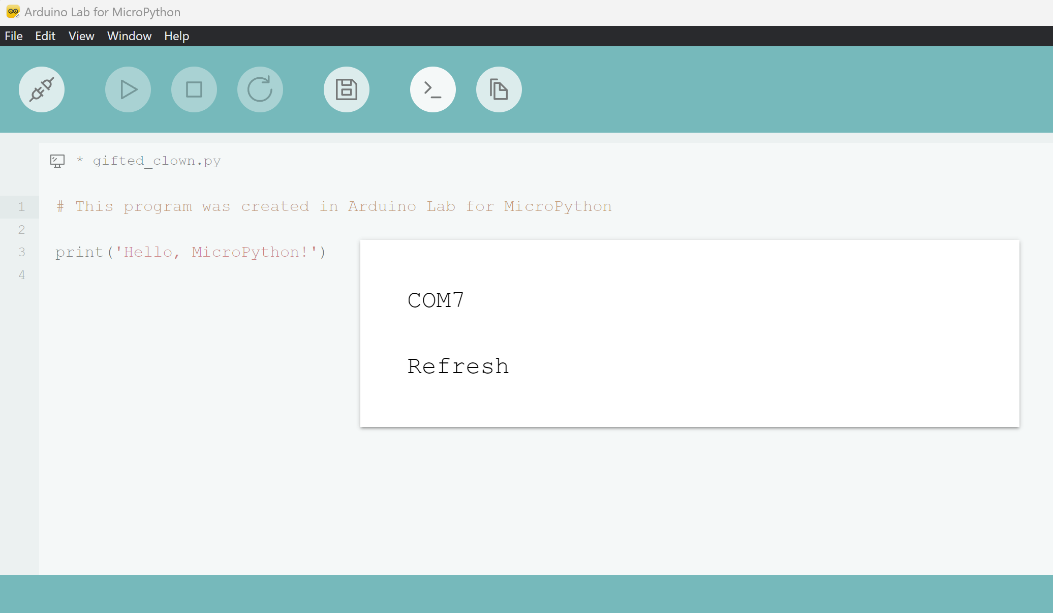
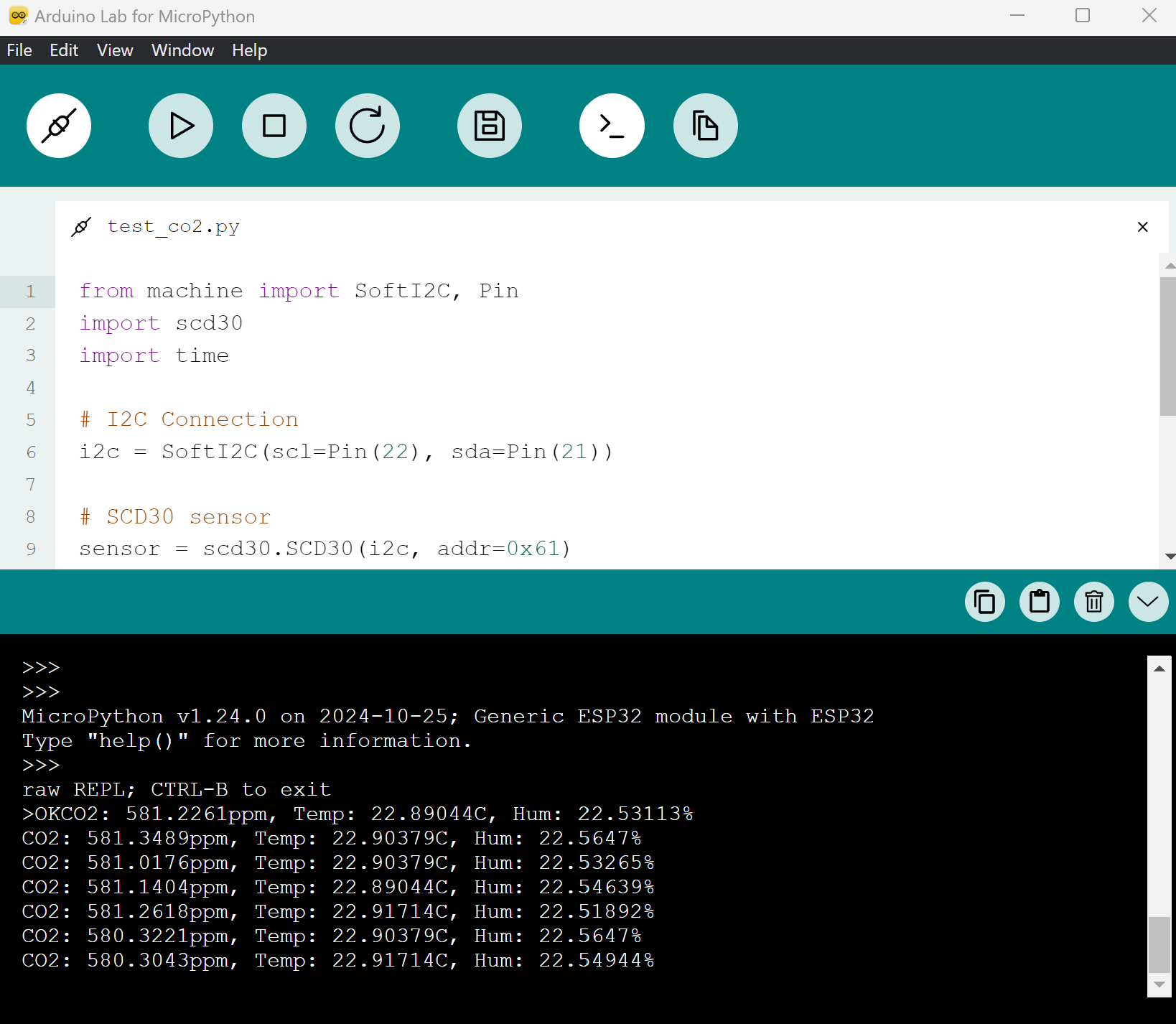
Arduino Lab is a lightweight editor to connect with an Arduino board, upload code, transfer files, and interact with a REPL (read–eval–print loop) terminal. The following is an example of collecting CO2 data from the SCD30 sensor with an ESP32 WROOM.
Both Thonny and Arduino Lab for MicroPython offer an Integrated Development Environment (IDE).
✅ Activity
There are many inexpensive sensors to measure physical quantities.
- Air Pressure BMP280
- CO2 Sensor SCD30 & SCD40
- Distance HC-SR04
- Distance VL53L0X
- Humidity DHT11/22 & BME280
- Light Intensity
- Location GY-GPS6MV2
- Temperature MAX6675
For this activity, use a microcontroller (e.g. ESP32) and sensor(s) to record measurements. Visualize the data and extract actionable information from the measurements.
✅ Knowledge Check
1. What does the boot.py script do on the ESP32 when using MicroPython?
- Incorrect. The boot.py script initializes the ESP32, but it doesn't necessarily run a blinking LED program.
- Correct. The boot.py script runs whenever the ESP32 turns on, before any other script like main.py.
- Incorrect. The boot.py script doesn't erase the flash memory. It's a startup script.
- Incorrect. The boot.py script runs automatically whenever the ESP32 is powered on or restarted.
2. What is the primary purpose of MicroPython?
- Incorrect. MicroPython is designed for microcontrollers which are lightweight systems, not for heavy-duty server solutions.
- Correct. MicroPython can run on more capable microcontrollers and is valuable for quick prototyping.
- Incorrect. While MicroPython provides an alternative to traditional C code on microcontrollers, it is not designed to replace C++ in all applications.
- Incorrect. MicroPython is designed for microcontrollers, which means it operates within the constraints of these devices.
✅ Exercise: Record ESP32 Chip Temperature
In this exercise, you will:
- Load MicroPython firmware onto your ESP32 WROOM (see steps above).
- Run a MicroPython script that samples the on‑chip temperature once per second for 30 seconds.
- Save the data to a CSV file on the board, then copy it to your computer and plot temperature vs. time.
Instructions
- Connect your ESP32 WROOM to your computer and open Thonny (or Arduino Lab for MicroPython).
- Create a new file named chip_temperature.py on the ESP32 board.
- Paste the code below and run it. When finished, it will create a file named chip_temp.csv on the device.
import time
FILENAME = "chip_temp.csv"
DURATION_SEC = 30
INTERVAL_SEC = 1
def main():
# Start timing from 0 using ticks for robust timing
t0 = time.ticks_ms()
next_sample = t0
# Write CSV header
with open(FILENAME, "w") as f:
f.write("time_s,temp_c,temp_f\n")
# Loop for ~DURATION_SEC seconds, sampling every INTERVAL_SEC
while True:
elapsed_ms = time.ticks_diff(time.ticks_ms(), t0)
elapsed_s = elapsed_ms / 1000.0
if elapsed_s >= DURATION_SEC:
break
# Read raw on-chip temperature (MicroPython returns Fahrenheit)
temp_f = esp32.raw_temperature()
temp_c = (temp_f - 32.0) / 1.8
# Write one line to CSV: time (s), Celsius, Fahrenheit
f.write("{:.3f},{:.2f},{:.2f}\n".format(elapsed_s, temp_c, temp_f))
f.flush()
# Wait until the next 1-second boundary
next_sample = time.ticks_add(next_sample, int(INTERVAL_SEC * 1000))
# Sleep just enough to align to the next interval (protect against negative values)
remaining = time.ticks_diff(next_sample, time.ticks_ms())
if remaining > 0:
time.sleep_ms(remaining)
if __name__ == "__main__":
main()
Notes
- The ESP32’s internal sensor reports chip temperature (often several °C above ambient). It is intended for diagnostics, not precision ambient measurement.
- Sampling uses time.ticks_ms() for stable timing.
- The script stops automatically after 30 seconds.
Download the CSV to your computer
- Thonny: In the Files pane (bottom-right), open the ESP32 device, right‑click `chip_temp.csv` → Download to….
- Arduino Lab: Use the file manager to download `chip_temp.csv` from the device.
- Command‑line alternatives: tools such as `mpremote` (`mpremote fs cp :chip_temp.csv .`) or `rshell` can also copy files.
Plot temperature vs. time (on your computer)
You can use any plotting tool. For example, in regular Python on your computer:
import csv
import matplotlib.pyplot as plt
t, tc = [], []
with open("chip_temp.csv", newline="") as f:
r = csv.DictReader(f)
for row in r:
t.append(float(row["time_s"]))
tc.append(float(row["temp_c"]))
plt.figure()
plt.plot(t, tc, marker=".")
plt.xlabel("Time (s)")
plt.ylabel("Chip Temperature (°C)")
plt.title("ESP32 Chip Temperature vs Time")
plt.grid(True)
plt.show()
What to Turn In
- A sentence describing your setup (board model, firmware version, tools used).
- Your chip_temperature.py script (final version you ran).
- Your chip_temp.csv file (30 seconds of data at 1 Hz).
- A plot of temperature vs. time with labeled axes and a brief (2–3 sentences) interpretation of what you observe (e.g., warming trend, stability, noise).