Electrical Circuit Principles


Electrical circuits are at the heart of modern instrumentation and control systems. Sensors and actuators used in chemical processes rely on electrical components to convert physical signals to measurable voltages or currents and to drive valves or heaters. This page builds on the fundamentals of voltage, current, resistance, capacitance, and inductance and expands into semiconductor devices (diodes). Examples and exercises help you design and analyze simple circuits.
⚡ Voltage, Current, Resistance, Capacitance and Inductance
Voltage is the electrical potential difference between two points and represents the pressure that drives charge through a circuit. Current is the rate of electric charge flow and is analogous to water flow in a pipe. Resistance quantifies how strongly a material opposes current. Ohm’s law relates these quantities by `V=IR`, where `V` is voltage, `I` is current, and `R` is resistance. Capacitance measures a component’s ability to store electric charge. An inductor stores energy in a magnetic field and resists changes in current.
- Voltage (V): Potential energy difference that pushes charges. Example: a 9 V battery has a 9‑volt potential difference.
- Current (I): Rate of charge flow. Example: if 6 C of charge pass a point in 3 s, the current is `6/3=2\text{ A}`.
- Resistance (R): Opposition to current flow. Ohm’s law `I=V/R` allows you to compute current given a voltage and resistance.
- Capacitance (C): Ability to store charge `Q` at a voltage `V` with `Q=CV`.
- Inductance (L): Ability to store energy in a magnetic field. An inductor opposes changes in current.
The energy stored in a capacitor is `\frac{1}{2}CV^{2}`, or equivalently `\frac{1}{2}QV` or `\frac{Q^{2}}{2C}`. The energy stored in an inductor is `\frac{1}{2}LI^{2}`.
Ohm’s Law and Power
Ohm’s law relates voltage, current and resistance as `V=IR`. From this law you can determine any one quantity if the other two are known. Power is the rate at which energy is converted or consumed. Electrical power `P` in a resistor is `P=VI=I^{2}R=V^{2}/R`.
🔢 Example: A 10 Ω resistor connected across a 5 V source carries `I=V/R=0.5\text{ A}` and dissipates `P=I^{2}R=2.5\text{ W}` as heat.
Kirchhoff’s Laws
- Kirchhoff’s Current Law (KCL): The sum of currents entering a node equals the sum leaving. In other words, the algebraic sum of currents at a junction is zero. For example, if `I_{1}=3\text{ A}` and `I_{2}=2\text{ A}` flow into a node, then the outgoing current must be `I_{1}+I_{2}=5\text{ A}`.
- Kirchhoff’s Voltage Law (KVL): The algebraic sum of all voltage drops around any closed loop equals zero. In a loop containing a battery and resistors, the sum of resistor voltage drops equals the battery voltage. Going around the loop yields zero net voltage.
🔢 Example: In a loop with a 12 V battery and two resistors (`R_{1}=2\Omega`, `R_{2}=4\Omega`) in series, the current is `I=12/(2+4)=2\text{ A}`. Voltage drops are `I R_{1}=4\text{ V}` and `I R_{2}=8\text{ V}`. Summing gives `12\text{ V}`, satisfying KVL.
Fundamental Components
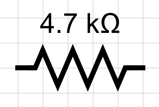
- Resistors 🛑: Oppose current and convert electrical energy to heat. The current through a resistor is `I=V/R`. Resistance is measured in Ohms (`\Omega`). The diagram below shows a `4700 \Omega`, or `4.7 k\Omega` resistor.
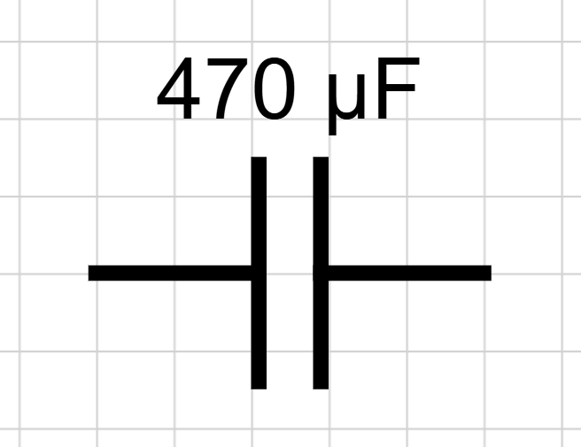
- Capacitors 🌀: Store energy as electric charge. A capacitor in DC circuits behaves like an open circuit when fully charged. Capacitance is measured in Farads. The diagram below shows a 470 µF capacity that is equal to 470 × 10⁻⁶ F or 0.000470 F. The charge on a capacitor is `Q=CV`, the energy stored is `\frac{1}{2}CV^{2}`, and the current flow to or from the capacitor is proportional to the rate of change of voltage.
$$I=C\,\frac{\mathrm{d}V}{\mathrm{d}t}$$
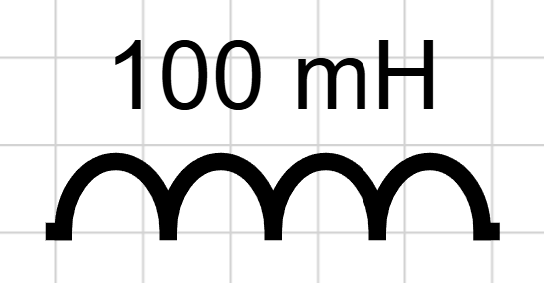
- Inductors 🔄: Store energy in a magnetic field and resist changes in current. Inductance is measured in Henrys. The diagram below shows a 100 mH inductor that is equal to 0.100 H. The stored energy is `\frac{1}{2}LI^{2}` and the voltage across an inductor is proportional to the rate of change of the current.
$$V=L\,\frac{\mathrm{d}I}{\mathrm{d}t}$$
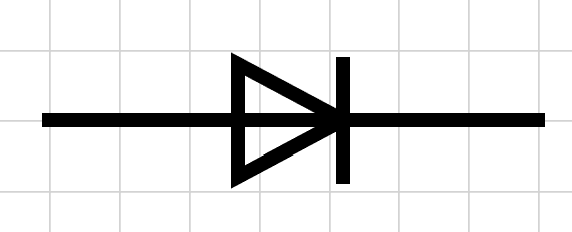
- Diodes ➡️: Semiconductor devices that allow current to flow primarily in one direction. In a forward-biased condition, a diode conducts with a small voltage drop (≈0.7 V for silicon). In reverse bias it blocks current. Diodes are used for rectification (converting AC to DC), signal clamping and protection.
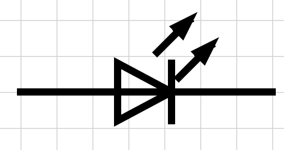
- LEDs 💡: Light‑emitting diodes are diodes that emit light when forward biased. They have a forward voltage drop (1.8–3.3 V depending on color). Use a resistor to limit current as shown in Exercise 1.
Breadboards & Building Circuits 🤖
Breadboards allow you to build and test circuits without soldering.
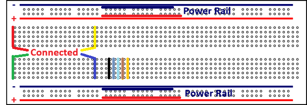
The holes in the horizontal row the breadboard are electrically connected to provide power and ground. The vertical rails are electrically connected with two aisles that are not connected across the horizontal middle.
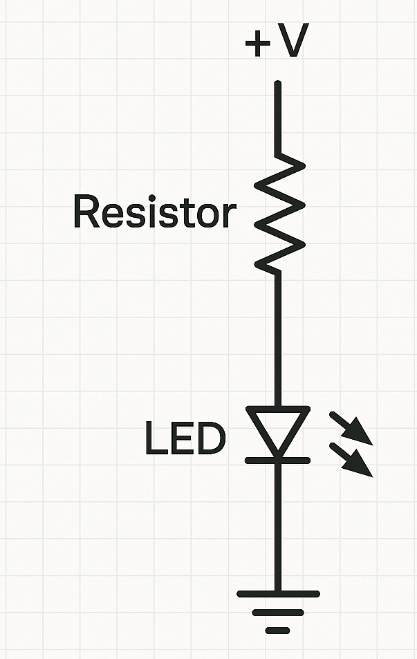
- LED with resistor: Connect the anode of an LED to a resistor, then to a positive supply. Connect the cathode to ground. Choose the resistor using Ohm’s law so that the LED current is within its rating (see Exercise 1).
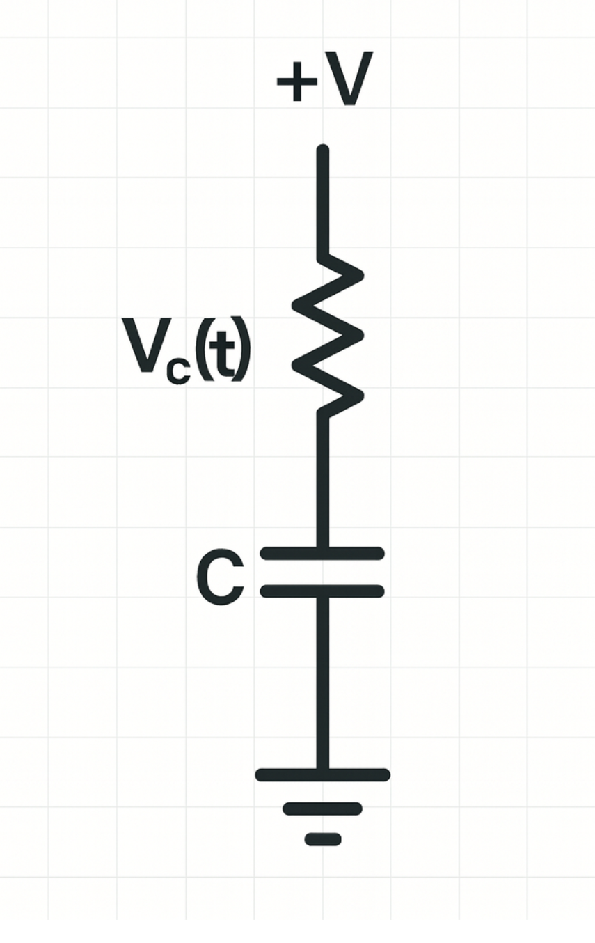
- RC timing circuit: A resistor and capacitor in series connected to a supply form an RC circuit. The voltage across the capacitor follows `V_{c}(t)=V_{s}[1-e^{-t/(RC)}]`, charging toward the supply value with time constant `\tau=RC`.
Simulating Circuits with Python 📊
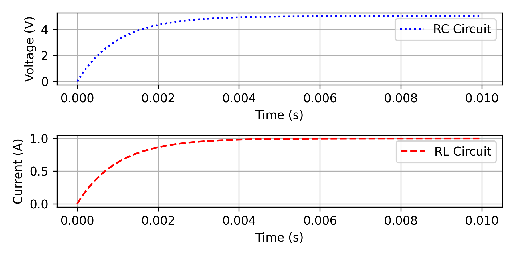
Python with libraries such as NumPy and Matplotlib is a powerful tool for simulating circuits. The code below simulates the step response of an RC circuit and an RL circuit.
import matplotlib.pyplot as plt
# RC circuit parameters
R = 1e3 # ohms
C = 1e-6 # farads
V_in = 5 # step voltage (V)
t = np.linspace(0, 0.01, 1000) # 0–10 ms
Vc = V_in * (1 - np.exp(-t / (R * C))) # capacitor voltage
Ic = (V_in/R) * np.exp(-t / (R * C)) # resistor current
# RL circuit parameters
L = 10e-3 # inductance (H)
R_L = 10 # ohms
I_in = 1 # step current source (A)
tr = np.linspace(0, 0.01, 1000)
Ir = I_in * (1 - np.exp(-R_L * tr / L)) # inductor current
Vr = L * (I_in / L) * np.exp(-R_L * tr / L) # voltage across inductor
# Plot results
plt.figure(figsize=(6, 3))
plt.subplot(2,1,1)
plt.plot(t, Vc, 'b:', label='RC Circuit')
plt.xlabel('Time (s)')
plt.ylabel('Voltage (V)')
plt.legend(); plt.grid(True)
plt.subplot(2,1,2)
plt.plot(tr, Ir, 'r--', label='RL Circuit')
plt.xlabel('Time (s)')
plt.ylabel('Current (A)')
plt.legend(); plt.grid(True)
plt.tight_layout(); plt.savefig('RC_RL_circuits.png',dpi=300)
plt.show()
Example Problems & Case Studies 🎯
Case Study 1: Diode Rectifier
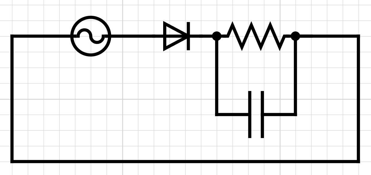
A 10 V peak AC supply is connected to a diode and load resistor. When the diode is forward biased, it conducts and drops about 0.7 V, so the load sees approximately 9.3 V peak. During the negative half cycle the diode blocks current, so the output is zero. Adding a capacitor across the load smooths the output, producing a DC voltage with ripple.
Case Study 2: Energy Stored in Reactive Components
- An inductor of 10 H carrying 3 A stores energy `W=\frac{1}{2}LI^{2}=\frac{1}{2}(10)(3^{2})=45\text{ J}`.
- A 100 μF capacitor charged to 50 V stores `E=\frac{1}{2}CV^{2}=0.5\times 100\times10^{-6}\times 50^{2}=0.125\text{ J}`.
Quiz: Circuit Fundamentals & Components
Test your understanding with the following questions. Click "Select" to reveal the answer.
1. Which statement best describes a diode?
Incorrect. Diodes conduct in one direction when forward biased and block in the opposite direction.
Correct. Silicon diodes conduct when forward biased with ≈0.7 V drop and block in reverse.
Incorrect. That describes an operational amplifier, not a diode.
Incorrect. Diodes do not intentionally store energy.
2. A 50 μF capacitor charged to 100 V stores:
Correct. `E=0.5\times 50\times10^{-6}\times 100^{2}=0.25\text{ J}`.
Incorrect. Use `E=\frac{1}{2}CV^{2}`.
Incorrect. The energy stored is proportional to capacitance and the square of voltage.
Incorrect. The result is far smaller for microfarad-scale capacitors at moderate voltages.
3. In a node where 2 A flows in through one branch and 3 A flows out through another branch, what must happen to satisfy KCL?
Incorrect. At a node the sum of currents entering must equal the sum leaving.
Correct. Currents entering (2 A) minus currents leaving (3 A + I) = 0 gives `I= -1\text{ A}`, meaning 1 A enters.
Incorrect. Check the algebraic sum of currents.
Incorrect. Charges cannot disappear. They must be conserved at the node.
Exercises
The following exercises provide practice with circuit analysis, component sizing and design.
Exercise 1 (15 min): LED Current‑Limiting Resistor
A red LED has a forward voltage of 2.0 V and maximum current of 20 mA. It is connected to a 9 V battery through a resistor.
Tasks:
- Determine the minimum resistor value to keep the LED current at or below 20 mA.
- Compute the power dissipated in the resistor.
- If the next standard resistor value available is 470 Ω, what is the actual LED current?
Solution
- The voltage across the resistor is `V_{R}=9\text{ V}-2.0\text{ V}=7.0\text{ V}`. Using Ohm’s law `R=V/I`, the minimum resistance is `7.0\text{ V}/0.020\text{ A}=350\Omega`. Choose the next higher standard value to avoid exceeding the limit.
- At 20 mA with 7 V across it, the resistor dissipates `P=V \times I=7\times0.020=0.14\text{ W}`. Use a resistor rated ≥0.25 W.
- Using 470 Ω, the current is `I=7/470\approx0.0149\text{ A}=14.9\text{ mA}`. The LED runs safely below its maximum current.
Exercise 2 (25 min): RC and RL Transient Response
For the RC and RL circuits used in the Python simulation above, the time constants are `τ_{\text{RC}}=RC` and `τ_{\text{RL}}=L/R`. Let `R=1\text{ kΩ}`, `C=2\text{ μF}`, `L=50\text{ mH}`, `R_{L}=25\text{ Ω}`.
Tasks:
- Compute the time constants `τ_{\text{RC}}` and `τ_{\text{RL}}`.
- At `t=2τ`, what percentage of the final value has the capacitor voltage reached in the RC circuit?
- At `t=2τ`, what percentage of the final current has the inductor current reached in the RL circuit?
Solution
- `τ_{\text{RC}}=RC=(1000\Omega)(2\times10^{-6}\text{ F})=2\times10^{-3}\text{ s}=2\text{ ms}`.
- `τ_{\text{RL}}=L/R_{L}=(50\times10^{-3}\text{ H})/25\Omega=2\times10^{-3}\text{ s}=2\text{ ms}`.
- The capacitor voltage follows `V_{c}(t)=V_{s}[1-\text{e}^{-t/τ}]`. At `t=2τ`, `V_{c}=V_{s}[1-\text{e}^{-2}]\approx0.8647\,V_{s}` or about 86.5% of the final value.
- The inductor current follows `I(t)=I_{s}[1-\text{e}^{-t/τ}]` (for a step current source). At `t=2τ`, the current reaches the same fraction as the capacitor voltage: about 86.5% of the final steady-state value.
Understanding these principles and practicing with simple circuits prepares you to design and analyze complex instrumentation involving sensors, actuators and control systems. Experiment with breadboards, simulation, and measurement tools to build intuition before moving on to advanced electronics.