Actuators
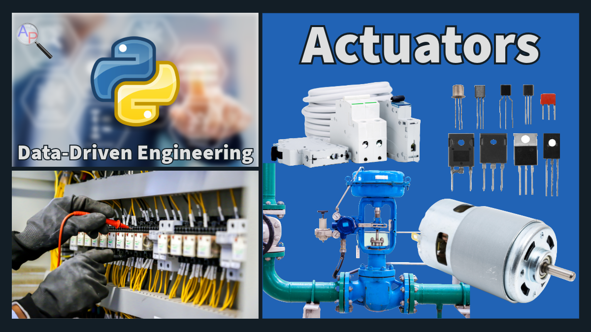


Actuators convert electrical signals into physical actions, such as movement or switching, which are essential components in automation, robotics, and industrial processes. Types of actuators commonly used include servos, relays, motors, solid-state relays, transistors, operational amplifiers, valves, pumps, blowers, electrical switches, and heaters. In industrial automation systems, these actuators play critical roles in regulating flows, controlling pressure, managing heat, and ensuring the proper operation of large-scale equipment.
Valve design ensures adequate control of liquid or gas flow rate of a fluid. Pumps and blowers provide the driving force for the fluids and can be regulated with variable speed controllers. Electrical switches enable the on/off control of electrical devices, and heaters regulate temperatures in chemical reactions or production processes. These components are often integrated with sophisticated monitoring and control systems to ensure safe and efficient operation.
Learning with simple and safe actuators like servos and relays allows students and engineers to understand practical issues that are crucial in industrial applications. These include actuator response time, which refers to how quickly an actuator can complete a task after receiving a command, and actuator monitoring, which ensures that the desired change is accurately made and sustained. Another key concept is actuator saturation limits, where the actuator may reach its maximum capacity and be unable to perform beyond a certain point, potentially impacting system performance. By working with simple actuators, students get hands-on experience with concepts like signal feedback, error detection, and the impact of mechanical constraints on control systems. This foundational knowledge prepares for more complex and high-stakes automation systems used in industrial settings, where actuator reliability, efficiency, and safety are critical.
- Electromagnetic Relay
- Used in home automation and robotics projects.
- Can handle up to 10A at 250VAC or 30VDC.
- Control applications where audible feedback, electrical isolation, and cost-efficiency are preferred.
- Solid State Relays
- MOSFET-based relays are ideal for high-speed switching in digital circuits.
- BJTs in H-Bridge modules provide high current capacity, suitable for DC motors.
Fundamental Components
- Transistors 🔁 Transistors are semiconductor devices that act as electronic switches or amplifiers. They come in two main types: bipolar junction transistors (BJTs), which are current-controlled and excel in analog amplification, and metal-oxide-semiconductor field-effect transistors (MOSFETs), which are voltage-controlled and dominate in digital circuits and power electronics due to their efficiency and high input impedance.
- Bipolar junction transistors (BJTs) act as current‑controlled switches or amplifiers. In an NPN transistor, a small base current controls a larger collector current such that the DC current gain β is `β=I_{c}/I_{b}`. Typical β values range from 50–200. The base–emitter junction behaves like a diode with a forward drop ≈0.7 V. Therefore a small base current (tens of microamps) can switch milliamp‑level collector currents.
- Metal–Oxide–Semiconductor Field-Effect Transistors (MOSFETs) act as voltage-controlled switches or amplifiers. Unlike BJTs, which are current-driven, a MOSFET’s gate draws essentially no steady-state current because it is insulated from the channel by a thin oxide layer. The drain current is controlled by the gate-to-source voltage `V_{gs}`. In an n-channel enhancement MOSFET, the device is normally off when `V_{gs}=0`. Once `V_{gs}` exceeds the threshold voltage `V_{th}`, a conductive channel forms and current flows from drain to source. The drain current in saturation is approximately
$$I_{d}=\tfrac{1}{2}k(V_{gs}-V_{th})^{2}$$
- Operational Amplifiers 🔈: An op‑amp is a high‑gain differential amplifier with an inverting (−) and non‑inverting (+) input. When used with negative feedback, op‑amps implement precise gain and mathematical operations. Op‑amps ideally have infinite input impedance and zero output impedance.
- In an inverting amplifier, the gain is `A_{v}=-R_{2}/R_{1}`, where `R_{1}` is the input resistor and `R_{2}` the feedback resistor.
- In a non‑inverting amplifier, the gain is `A_{v}=1+R_{2}/R_{1}`.
Breadboards & Building Circuits 🤖
- Transistor switch: An NPN transistor can switch a load. Connect the collector to the load and then to the supply. Apply a small base current (through a resistor) to turn the transistor on, allowing current from collector to emitter.
- Op‑amp amplifier: Use an op‑amp with ± supply rails (or single‑supply with virtual ground). For an inverting amplifier with gain −10, use an input resistor `R_{1}` and feedback resistor `R_{2}=10R_{1}`. Connect the non‑inverting input to ground.
Case Study 1: NPN Transistor Switch
A control system needs to drive a 100 mA solenoid. The microcontroller pin can supply only 5 mA. Using an NPN transistor with β=100 and `V_{BE}=0.7\text{ V}`, the base current needed is `I_{b}=I_{c}/β=0.1/100=1\text{ mA}`. Choose a base resistor so that when the input pin provides 5 V, the base current is ≈1 mA: `R_{B}=\frac{(5-0.7)}{1}\frac{\text{V}}{\text{mA}}≈4.3\text{ kΩ}`.
Case Study 2: Inverting Amplifier Design
Design an inverting op‑amp circuit with gain −10. Using `A_{v}=-R_{2}/R_{1}`, choose `R_{1}=5\text{ kΩ}` and `R_{2}=50\text{ kΩ}`. If an input signal of 0.2 V is applied, the output will be −2 V. Because op‑amps saturate when the output approaches the supply rails, ensure the supply is at least ±5 V.
Applications
Actuators are found in:
- Home Automation: Controlling lights, blinds, and other devices.
- Robotics: Motor control for movement and object manipulation.
- Prototyping: For building and testing automation systems.
- Industrial control: Process control systems use valves and pumps to regulate flow, pressure, temperature, and other key manufacturing conditions.
Safety and Precautions
- Ensure appropriate voltage and current ratings for each actuator.
- Be mindful of heat dissipation, especially with high power loads.
- Double-check wiring and follow proper safety practices to prevent short circuits.
Quiz: Circuit Fundamentals & Components
Test your understanding with the following questions. Click "Select" to reveal the answer.
1. For an inverting op‑amp circuit with `R_{1}=1\text{ kΩ}` and `R_{2}=9\text{ kΩ}`, the voltage gain is:
Incorrect. The inverting amplifier has a negative gain equal to `-R_{2}/R_{1}`.
Correct. The gain is `A_{v}=-R_{2}/R_{1}=-9/1=-9`.
Incorrect. Check the ratio `R_{2}/R_{1}`.
Incorrect. The magnitude of the gain is the ratio of the resistors.
Exercise 1 (20 min): Transistor Base Resistor
Design a transistor switch using an NPN transistor (β = 100, `V_{BE}=0.7\text{ V}`) to drive a 12 V, 120 mA lamp from a microcontroller that outputs 5 V with a maximum output current of 5 mA.
Tasks:
- Calculate the required base current to saturate the transistor.
- Compute the base resistor value that ensures the transistor saturates without exceeding the microcontroller current limit.
- Suggest a suitable power rating for the transistor’s collector resistor (lamp).
Solution
- The collector current is 0.12 A. With `β=100`, the base current needed is `I_{b}=I_{c}/β=0.12/100=1.2\text{ mA}`.
- The base resistor must drop `V_{R}=5\text{ V}-0.7\text{ V}=4.3\text{ V}` at 1.2 mA, so `R_{B}=4.3\text{ V}/0.0012\text{ A}\approx3.6\text{ kΩ}`. To limit the microcontroller current to ≤5 mA, choose a resistor of ≈4.7 kΩ. This reduces the base current but still saturates because the effective β in saturation is lower (around 20–50).
- The lamp dissipates `P=V I=12\text{ V}\times0.12\text{ A}=1.44\text{ W}`, so the transistor must handle at least this power. Use a transistor with power rating >2 W or provide a heat sink.
Exercise 2 (20 min): Op‑Amp Summing Amplifier
You need to build a summing amplifier that outputs `V_{\text{out}} = -\left(\frac{R_{f}}{R_{1}}V_{1} + \frac{R_{f}}{R_{2}}V_{2}\right)` using an op‑amp. Let `R_{1}=10\text{ kΩ}`, `R_{2}=20\text{ kΩ}`, and `R_{f}=30\text{ kΩ}`.
Tasks:
- If `V_{1}=0.5\text{ V}` and `V_{2}=1\text{ V}`, compute `V_{\text{out}}`.
- Explain why the output is inverted.
- Suggest how to make a non‑inverting summer.
Solution
- The gains are `-R_{f}/R_{1}=-30/10=-3` and `-R_{f}/R_{2}=-30/20=-1.5`. Therefore `V_{\text{out}}= -3(0.5) -1.5(1) = -1.5 -1.5 = -3.0\text{ V}`.
- The inverting summing amplifier uses the op‑amp’s inverting input, so all weighted inputs are inverted relative to ground. The negative sign arises from the phase inversion.
- A non‑inverting summing amplifier can be built by summing signals through a resistor network to a node and feeding that node to the non‑inverting input. Use an op‑amp buffer to provide high input impedance and gain `A_{v}=1+R_{2}/R_{1}`.
Exercise 3: MOSFET‑Controlled LED: Blink and PWM Brightness
Goal: Use an N‑channel logic‑level MOSFET as a low‑side switch to drive an LED from 5 V. First blink it on/off with a digital signal, then use PWM to ramp brightness from 0% to 100% and back.
Parts
- 1× N‑channel logic‑level MOSFET (e.g., RFP30N06LE or similar)
- 1× LED
- R1: 330 Ω (LED series resistor)
- R2: 10 kΩ (gate pulldown to GND)
- Breadboard + jumpers
- Microcontroller running MicroPython (ESP32), using Pin 5 as the gate signal (Sig)
Wiring Diagram

- Connect LED anode to 5 V through R1 (330 Ω).
- Connect LED cathode to the MOSFET Drain.
- Connect MOSFET Source to GND.
- Connect R2 (10 kΩ) from the MOSFET Gate to GND (pulldown ensures OFF when no signal).
- Connect microcontroller Pin 5 (Signal) to MOSFET Gate. Also connect microcontroller GND to the 5 V supply GND (common ground).
Part A: Blink (digital on/off)
Verify your wiring by turning the MOSFET fully on and off using a digital output.
import time
from machine import Pin
gate = Pin(5, Pin.OUT) # MOSFET gate
while True:
gate.value(1) # LED ON (MOSFET conducting)
time.sleep(0.5)
gate.value(0) # LED OFF
time.sleep(0.5)
Part B: PWM ramp 0→100%→0
Swap the digital write for PWM to control brightness. On ESP32 MicroPython, PWM duty ranges 0–1023 by default.
import time
from machine import Pin, PWM
# 1 kHz PWM is a good default for visible LEDs
pwm = PWM(Pin(5), freq=1000, duty=0)
delay = 0.005
# Up: 0% -> 100%
for d in range(0, 1024): # 0..1023
pwm.duty(d)
time.sleep(delay)
# Down: 100% -> 0%
for d in range(1023, -1, -1):
pwm.duty(d)
time.sleep(delay)
pwm.deinit()
Tasks
- Blink test: Run the Part A script and confirm the LED blinks.
- PWM ramp: Run the Part B script and confirm a smooth fade in and out.
- Modify: Change the PWM frequency (e.g., 500 Hz, 2 kHz) and comment on any visible flicker.
Troubleshooting
- If the LED never turns off, check the 10 kΩ pulldown from Gate→GND and confirm grounds are common.
- If the LED is dim or inconsistent, verify the LED orientation, R1 value, and that your MOSFET is logic‑level.
- If nothing lights, double‑check that the Drain, Source, and Gate pins match your MOSFET’s pinout.
What to Turn In
- Complete Exercises 1-3
- For Exercise 3:
- A short note (3–5 sentences) describing your wiring and observations (blink + PWM).
- The modified PWM script you created (frequency change and/or custom ramp).
- A 10-15 s video or photo showing the LED ramping in brightness.