Electromagnetic Relay Module
Channel Relay Module SRD-5VDC-SL-C
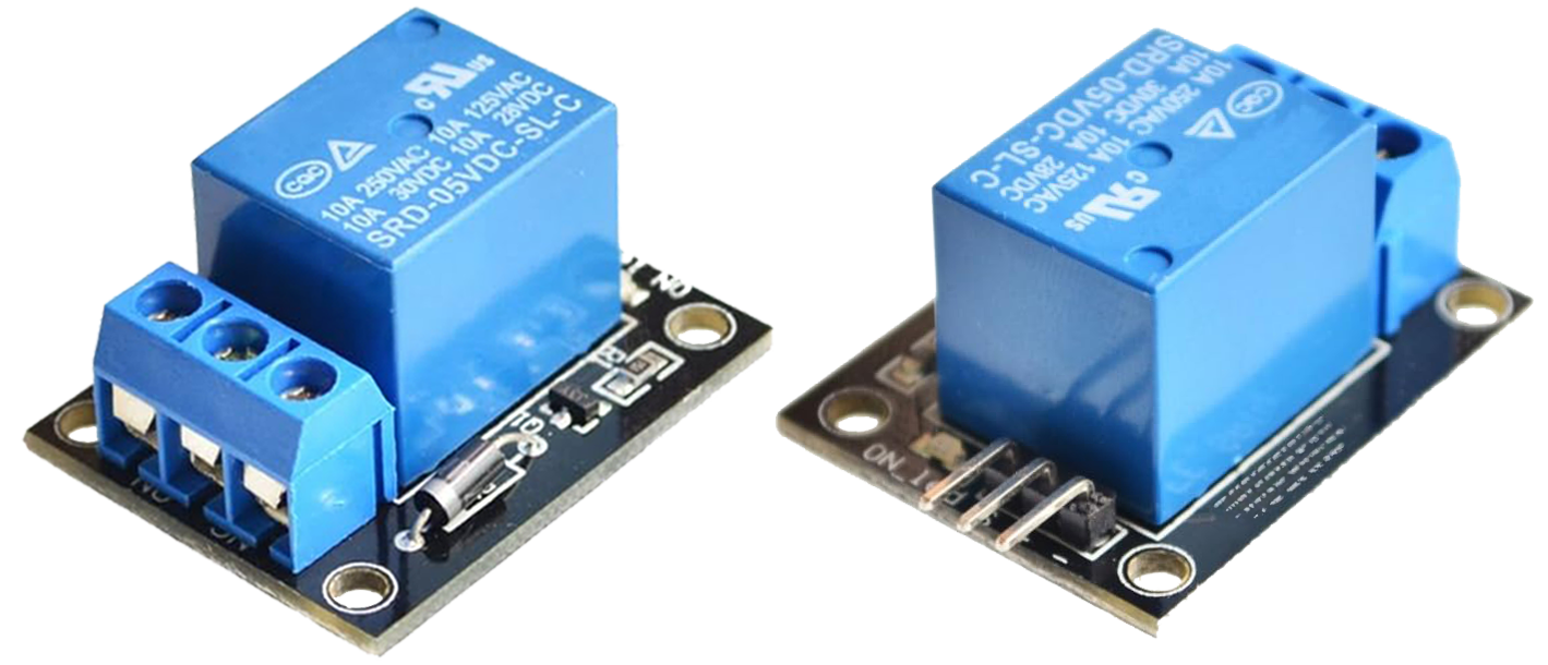
The SRD-5VDC-SL-C is a small relay module used in various automation and robotics projects. It is capable of handling significant power loads up to 10A at 250VAC, 125VAC, and 30VDC. This relay module is suitable for many robotic, home automation, and benchtop prototype applications for controlling devices.
Connections and Operation
- DC+ and DC-: Power terminals for the relay coil, operating at 5VDC.
- IN (Input Signal): The control signal from a microcontroller (e.g. Arduino or ESP32) activates the relay when high.
- NO, COM, NC: The switch terminals for Normally Open, Common, and Normally Closed configurations.
Use Normally Open (NO) when the switch should be in the open position when the coil loses power. Use the Normally Closed (NC) when the switch should be in the closed position by default when no signal is applied to the switch.
Input Voltage and Range
The relay module operates with a 5VDC coil voltage (12VDC is also available) and can switch up to 10A at voltages at 30VDC or 250VAC. This is like a light switch in a home that turns on/off an appliance or lighting.
Mechanism and Benefits
Electromechanical relays use an electromagnet to activate the switch and produce a characteristic click. Compared to solid-state relays, it offers audible feedback, better electrical isolation, cost-effectiveness, lower heat generation with the switch, and simple on/off control. It is not desirable for frequent applications that require frequent switching such as Pulse Width Modulation (PWM). Electromechanical relays are particularly useful in systems involving motors and transformers that demand high startup amps with initial large currents. The mechanical nature is not suitable for environments with high vibration or for applications requiring extremely rapid switching.
Solid-state relays are ideal for high-speed and frequent switching operations, making them suitable for applications that demand rapid and repetitive control. They are also preferred in high-vibration environments due to their lack of moving parts, which enhances durability and reliability. Additionally, solid-state relays are beneficial when placed near sensitive automation components such as measurement devices (e.g. thermocouples) because they have less electromagnetic interference.
import time
# Setup Relay (Adjust Pin number if needed)
relay_pin = Pin(23, Pin.OUT)
relay = Pin(relay_pin)
# Test the relay
relay.value(1) # Activate relay
time.sleep(1)
relay.value(0) # Deactivate relay
In this example, the `relay.value()` function controls the relay using an ESP32. The function takes a state argument to set the relay either ON or OFF.
Application
This relay module is used for home automation projects like controlling lights and appliances and can also be used in robotics for controlling larger loads. For this introductory exercise, use a relay switch module to turn on and off an LED light.
To successfully connect and operate a relay module (specifically the Channel Relay Module SRD-5VDC-SL-C) with an LED, and a microcontroller like the ESP32, follow these step-by-step instructions:
1. Gather the Components
- Channel Relay Module SRD-5VDC-SL-C
- Microcontroller (e.g., ESP32)
- LED
- Resistor (220 Ohm or similar)
- Breadboard and connecting wires
2. Connect the Relay Module to the Microcontroller
- DC+ and DC- Terminals: Connect these to a 5V power supply. The DC+ goes to the 5V pin and DC- to the ground (GND) on the microcontroller.
- IN (Input Signal): Connect this to a digital pin on the microcontroller (e.g., GPIO 23 on an ESP32). This pin controls the relay.
3. Prepare the LED Circuit
- Choose the Correct Resistor: Use a resistor (around 220 Ohms) in series with the LED to limit the current. This protects the LED from burning out.
- Connect the LED: Connect the longer leg of the LED (anode) to one side of the resistor, and connect the other side of the resistor to the NO (Normally Open) terminal of the relay.
- Complete the LED Circuit: Connect the shorter leg of the LED (cathode) to the COM (Common) terminal of the relay.
4. Code the Microcontroller
- Use the Python code above to control the relay with the ESP32.
5. Wiring with Electromagnetic Relay
- Ensure all connections are secure and that the relay coil is powered with 5V.
- The input signal from the microcontroller activates the relay, allowing the current to flow through the LED when the relay is in the NO position.
Safety and Precautions
- Double-check all connections before powering up the circuit.
- Ensure the LED is correctly positioned with the anode and cathode in the correct orientation.
- Do not exceed the voltage and current ratings of the relay module.