TCLab On/Off Control
 |  | |  |  | 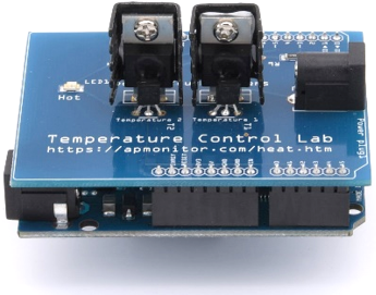 |
|---|
Objective: Generate data from an On/Off controller and determine the parameters of a 2nd order underdamped model that best fits the response.
On/off control is used in most cooling and heating applications where the actuator can only be On or Off. Run the temperature control lab with On/Off control for 4 minutes to reach a setpoint of 40oC.
On/Off Control (4 min)
import time
a = tclab.TCLab() # connect to TCLab
fid = open('data.csv','w')
fid.write('Time,Q1,T1\n')
fid.write('0,0,'+str(a.T1)+'\n')
fid.close()
for i in range(240): # 4 minute test
time.sleep(1)
T1 = a.T1 # temperature
Q1 = 100 if T1<=40.0 else 0 # On/Off Control
a.Q1(Q1) # set heater
print('Time: '+str(i)+' Q1: '+str(Q1)+' T1 (SP=40): '+str(T1))
fid = open('data.csv','a')
fid.write(str(i)+','+str(Q1)+','+str(T1)+'\n')
fid.close()
a.close()
Generate Plot
import pandas as pd
data = pd.read_csv('data.csv')
plt.figure(figsize=(10,7))
ax=plt.subplot(2,1,1); ax.grid()
plt.plot(data['Time'],data['Q1'],'b-',label=r'$Q_1$ (%)')
plt.legend(); plt.ylabel('Heater')
ax=plt.subplot(2,1,2); ax.grid()
plt.plot(data['Time'],data['T1'],'r-',label=r'$T_1$ $(^oC)$')
plt.legend(); plt.xlabel('Time (sec)'); plt.ylabel('Temperature')
plt.show()
Use a graphical method to fit a 2nd order model to the closed-loop response by finding `K_p`, `\zeta`, and `\tau_s`. Dead-time `\theta_p` is not needed for this model.
$$\tau_s^2 \frac{d^2T_1}{dt^2} + 2 \zeta \tau_s \frac{dT_1}{dt} + T_1 = K_p \, Q_1$$
Follow the steps to obtain a graphical approximation of a step response of the underdamped (oscillating) second order system. An underdamped system implies that `0 \ge \zeta > 1`.
- Find `\Delta T_1` from step response.
- Find `\Delta T_{SP}` as the input to the step response.
- Calculate `K_p = {\Delta T_1}/{\Delta T_{SP}`.
- Calculate damping factor `\zeta` from overshoot `OS` or decay ratio `DR`.
- Calculate `\tau_s` from equations for rise time `t_r`, peak time `t_p`, or period `P`.
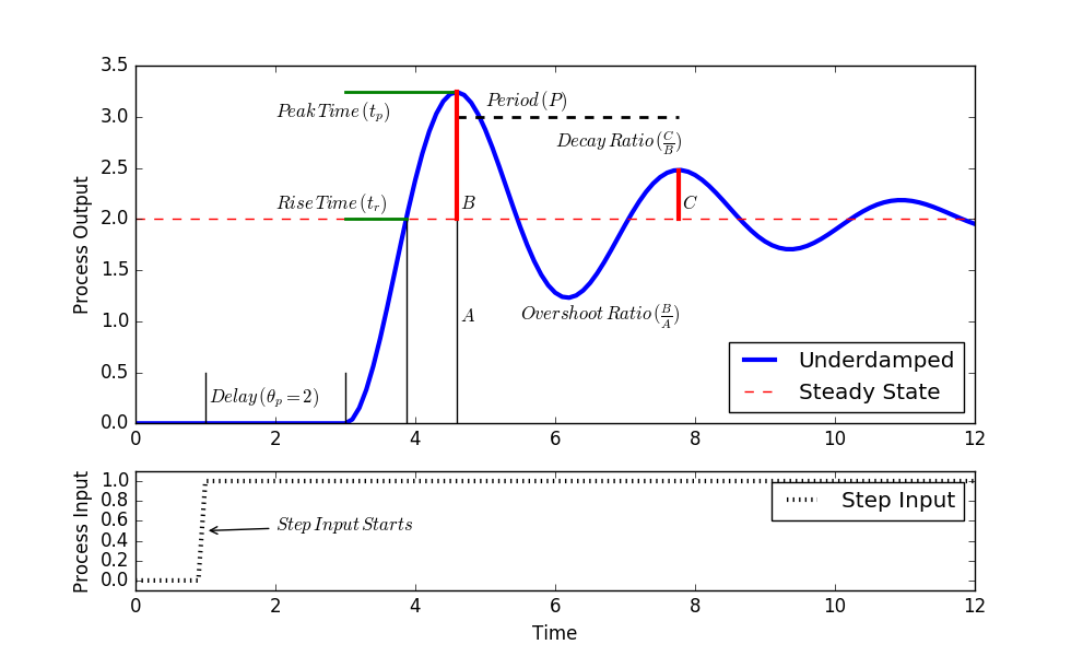
Add the underdamped `(0\le\zeta<1)` analytic solution to data plot to compare the graphical fit to the data. See Second Order Systems for additional information on analytic solutions.
$$T'_1(t) = K_p \Delta T_{SP} \left( 1-e^{-\zeta\,t/\tau_s} \left[ \cos\left( \frac{t}{\tau_s}\sqrt{1-\zeta^2} \right) + \frac{\zeta}{\sqrt{1-\zeta^2}} \sin\left( \frac{t}{\tau_s}\sqrt{1-\zeta^2} \right) \right] \right)$$
Solution
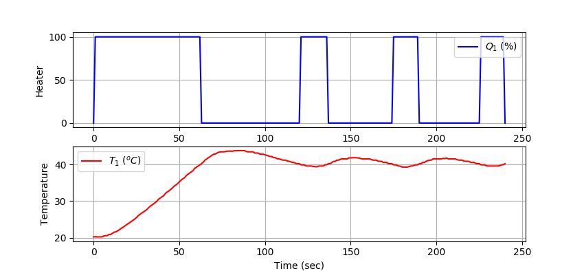
1. Find `\Delta T_1` from step response.
2. Find `\Delta T_{SP}` as the input of the step response.
3. Calculate `K_p = {\Delta T_1}/{\Delta T_{SP}`.
4. Calculate damping factor `\zeta` from overshoot `OS` or decay ratio `DR`.
$$\zeta = \sqrt{\frac{\left(\ln(OS)\right)^2}{\pi^2 + \left(\ln(OS)\right)^2}} = 0.527$$
5. Calculate `\tau_s` from the equation peak time `t_p`.
$$\tau_s = \frac{\sqrt{1-\zeta^2}}{\pi}t_p = 23.2$$
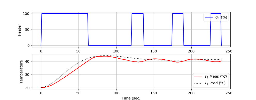
import pandas as pd
import numpy as np
data = pd.read_csv('data.csv')
# graphical fit
Delta_SP = 20
Delta_T1 = 21
OS = (44-41)/(41-20)
tp = 86.0
Kp = Delta_T1/Delta_SP
lnOS2 = (np.log(OS))**2
zeta = np.sqrt(lnOS2/(np.pi**2+lnOS2))
taus = tp * np.sqrt(1-zeta**2)/np.pi
print('Kp: ' + str(Kp))
print('zeta: ' + str(zeta))
print('taus: ' + str(taus))
# analytic solution
t = data['Time'].values
T0 = data['T1'].values[0]
a = np.sqrt(1-zeta**2)
b = t/taus
c = np.cos(a*b)
d = (zeta/a)*np.sin(a*b)
T1 = Kp*Delta_SP*(1-np.exp(-zeta*b)*(c+d))+T0
plt.figure(figsize=(10,7))
ax=plt.subplot(2,1,1); ax.grid()
plt.plot(data['Time'],data['Q1'],'b-',label=r'$Q_1$ (%)')
plt.legend(); plt.ylabel('Heater')
ax=plt.subplot(2,1,2); ax.grid()
plt.plot(data['Time'],data['T1'],'r-',label=r'$T_1$ Meas $(^oC)$')
plt.plot(t,T1,'k:',label=r'$T_1$ Pred $(^oC)$')
plt.legend(); plt.xlabel('Time (sec)'); plt.ylabel('Temperature')
plt.show()
Generative AI Learning
Use these prompts to test your understanding after completing the exercise. Direct the AI - do not let it do the exercise for you.
App: Run on/off experiments with the TCLab Control Studio. Use manual mode toggling or an aggressive controller to create the limit cycle on the digital twin, then reproduce it on hardware and export both CSVs.
What to Turn In
- Item 1: Recorded On/Off control data file (data.csv) showing temperature and heater output over the 4-minute test.
- Item 2: Plot of measured heater output (Q₁) and temperature (T₁) versus time.
- Item 3: Calculations of ΔT₁, `ΔT_{SP}`, process gain (Kₚ), damping factor (ζ), and second-order time constant (τₛ) using the graphical method.
- Item 4: Analytic second-order underdamped model equation using the identified parameters.
- Item 5: Overlay plot comparing the measured T₁ response and the analytic model prediction.
- Item 6: Short discussion of how well the second-order model fits the On/Off control response and possible sources of deviation.
Submit a short report (PDF, 1-2 pages) that curates your results into a demonstration of what you learned. You may use Generative AI to help write the report, but you must guide it to the correct visualizations, justifications, and assumptions. Answer these questions:
- Include the on/off control plot with the deadband marked. Report the oscillation amplitude and period.
- What happened (measured, not guessed) when you changed the deadband, and why?
- Second-order behavior: where in your response do you see evidence of more than one thermal capacitance (sensor vs heater), and how does it show up in the limit cycle shape?
- From the quiz prompt: one question you missed and the corrected answer.