Solid State Relay Modules
Solid State Relay Modules: IRF520 & L298N
Solid State Relay Modules like IRF520 (MOSFET) and L298N (BJT) are popular in automation and robotics projects. These modules can control motors and other high-current applications. A MOSFET (Metal-Oxide-Semiconductor Field-Effect Transistor) and a BJT (Bipolar Junction Transistor) are two types of transistors used in electronic circuits, but they operate differently and have distinct characteristics.
MOSFET
1. Structure and Operation: A MOSFET is a field-effect transistor that includes a gate, drain, and source terminal. It uses an electric field to control the conductivity of a channel, typically made from a semiconductor material. The key component is the gate insulator, usually made of silicon dioxide or a similar material, which isolates the gate from the body of the transistor.
2. Types: There are two main types of MOSFETs: N-channel (which conducts when a positive voltage is applied to the gate) and P-channel (which conducts when a negative voltage is applied).
3. Voltage Control: MOSFETs are voltage-controlled devices, meaning the current flowing through them is controlled by the voltage applied to the gate terminal.
4. Applications: They are widely used in digital circuits, power applications, and analog switches due to their high input impedance and fast switching speeds.
BJT
1. Structure and Operation: A BJT is a current-controlled transistor that consists of three regions: emitter, base, and collector. It operates by using a small current at the base terminal to control a larger current flowing from the collector to the emitter.
2. Types: BJTs are divided into two types: NPN (where a layer of P-type material is sandwiched between two layers of N-type material) and PNP (the opposite arrangement).
3. Current Control: Unlike MOSFETs, BJTs are current-controlled devices. The output current is a function of the input current.
4. Applications: BJTs are commonly used in amplification and switching applications, particularly where a low input impedance is needed.
Although both MOSFETs and BJTs are fundamental in electronics, they differ significantly in the operational principles and typical applications. MOSFETs are generally preferred for high input impedance and efficiency in digital circuits, whereas BJTs are often used for the current amplification properties in analog circuits.
IRF520 Module
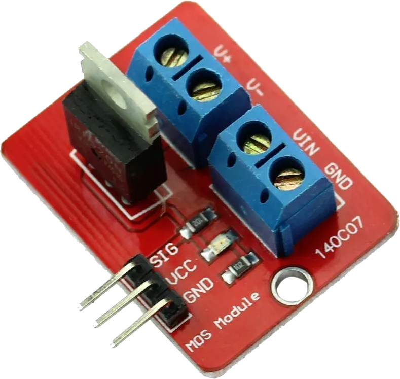
The IRF520 is a MOSFET-based module capable of controlling high power loads. MOSFETs are controlled by a voltage input for high switching speeds. They are suitable for low to medium power applications and have a lower current capacity than BJTs.
L298N Module
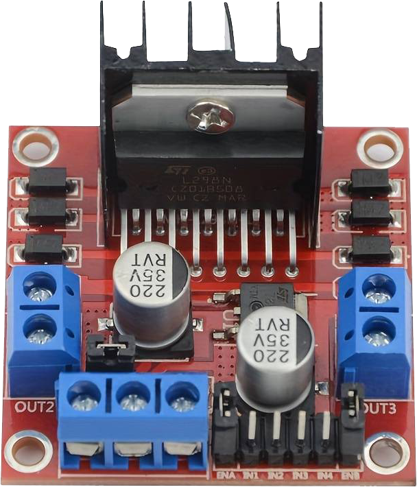
The L298N is a dual H-Bridge motor driver, often used for controlling the direction and speed of DC motors. It is a module capable of driving two DC motors or one stepper motor. The L298N uses BJT transistors with a higher current capacity than the IRF520. A MOSFET alternative to the L298N is the TB6612FNG module that has higher efficiency but lower current capability, similar to the IRF520 module.
The efficiency of both the IRF520 MOSFET module and the L298N BJT H-Bridge module depends on several factors, including the specific application, load characteristics, operating voltage, and current. The efficiency of a BJT is typically 60-80% while a MOSFET is typically 90-95% efficient. The BJT requires a larger power source to compensate for the inefficiency and more heat dissipation.
Benefits of MOSFET (IRF520) vs BJT (L298N) Transistors
- MOSFET (IRF520):
- Higher switching speed.
- Better for PWM applications.
- Lower power dissipation.
- Ideal for low to medium power loads.
- BJT (L298N):
- Higher current handling capability.
- More robust for high power applications.
- Simpler drive circuitry.
- Ideal for motor control applications.
MicroPython Code for Motor Control
# For IRF520
mosfet_pin = Pin(23, Pin.OUT)
motor_speed = PWM(mosfet_pin)
# Control motor speed (0-1023)
motor_speed.duty(512)
# For L298N
in1 = Pin(23, Pin.OUT)
in2 = Pin(22, Pin.OUT)
# Motor forward
in1.value(1)
in2.value(0)
# Motor reverse
in1.value(0)
in2.value(1)
This MicroPython code demonstrates basic motor control using the IRF520 and L298N modules with an ESP32. The IRF520 example controls the speed using PWM, while the L298N example shows how to reverse the motor direction.
Applications
These modules can be used in a variety of applications:
- Home automation systems for controlling blinds, fans, or pumps.
- Robotics projects for driving motors and actuators.
- Custom DIY projects where precise motor control is necessary.
Connection and Operation
The connection and operation of these modules:
- Ensure the correct voltage and current ratings for the motor.
- Use appropriate PWM frequencies for the IRF520.
- For the L298N, ensure correct wiring for motor direction control.
Safety and Precautions
- Always check the power ratings and ensure they match the motor requirements.
- Be cautious of heat generation in high-power applications.
- Double-check wiring to prevent short circuits.