Valve Design Exercise
 |  |  |  |  |
|---|
The flow rate of cooling fluid through a system is regulated by a valve. The pressure generated by the pump is constant.
$$\Delta P_{pump}=100 \,\mathrm{bar}$$
The cooling fluid has a specific gravity of 1.1. As a first step, characterize the valve without the system pressure drop. In a second step, determine the best valve trim for a linear relationship between lift and flow for the installed valve.
Part I: Valve Characterization
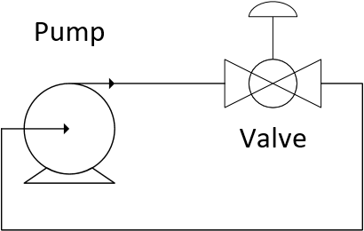
Plot the relationship between flow `q` and valve lift `l` for the valve characterized by the design equation.
$$q = C_v f(l) \sqrt{\frac{\Delta P_v}{g_s}}$$
with `C_v = 2` and either a linear lift function `f(l)=l` or an equal percentage lift function `f(l)=R^{l-1}` with `R=20`.
Solution, Part I
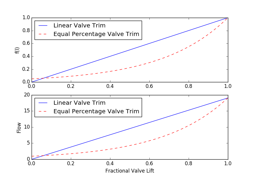
import matplotlib.pyplot as plt
## Lift functions for two different valve trim types
def f_lin(x):
return x # linear valve trim
def f_ep(x):
R = 20
return R**(x-1) # equal percentage valve trim (R = 20-50)
lift = np.linspace(0,1) # equally spaced points between 0 and 1
plt.figure(1) # create new figure
plt.title('Valve Performance - Not Installed')
plt.subplot(2,1,1) # 2,1 subplot with 1st window
plt.plot(lift,f_lin(lift),'b-') # linear valve
plt.plot(lift,f_ep(lift),'r--') # equal percentage
plt.ylabel('f(l)')
plt.legend(['Linear Valve Trim','Equal Percentage Valve Trim'])
g_s = 1.1 # specific gravity of fluid
def q(x,f,Cv,DPv):
return Cv * f(x) * np.sqrt(DPv/g_s) # flow through a valve
## Intrinsic valve performance
# no process equipment - all pressure drop is across valve
DPt = 100 # Total pressure generated by pump (constant)
Cv = 2 # Valve Cv
flow_lin = q(lift,f_lin,Cv,DPt) # flow with linear valve
flow_ep = q(lift,f_ep,Cv,DPt) # flow with equal percentage
plt.subplot(2,1,2) # 2,1 subplot with 2nd window
plt.plot(lift,flow_lin,'b-') # plot linear valve response
plt.plot(lift,flow_ep,'r--') # plot equal percentage valve
plt.ylabel('Flow')
plt.legend(['Linear Valve Trim','Equal Percentage Valve Trim'])
plt.xlabel('Fractional Valve Lift')
plt.show()
Part II: Installed Valve
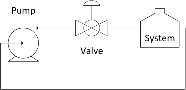
The pressure drop across the system (without the valve) follows the following correlation between pressure drop `\Delta P_{system}` and flow rate `q`.
$$\Delta P_{system} = 2 q^2$$
Plot the relationship between flow `q` and valve lift `l` for the system and valve with `C_v = 2` and either a linear lift function `f(l)=l` or an equal percentage lift function `f(l)=R^{l-1}` with `R=20`.



Solution, Part II
The first step in this solution is to relate the pressure drop across the valve and the system to the pressure generated by the pump.
$$\Delta P_{pump} = \Delta P_v + \Delta P_{system}$$
with
$$\Delta P_{pump} = 100$$
$$\Delta P_v = g_s \left(\frac{q}{C_v f(l)}\right)^2$$
$$\Delta P_{system} = 2 q^2$$
This gives a combined equation in terms of lift `l` and flow `q`.
$$100 = g_s \left(\frac{q}{C_v f(l)}\right)^2 + 2 q^2$$
Algebraic manipulation is then used to obtain flow as a function of lift `q(l)` for the valve and system.
$$q(l) = \sqrt{\frac{100\left(C_v f(l)\right)^2}{(g_s + 2 \left(C_v f(l)\right)^2)}}$$
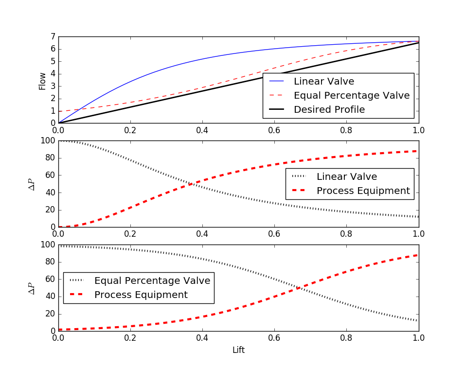
import matplotlib.pyplot as plt
DPt = 100 # Total pressure generated by pump (constant)
Cv = 2 # Valve Cv
g_s = 1.1 # specific gravity of fluid
lift = np.linspace(0,1) # equally spaced points between 0 and 1
## Lift functions for two different valve trim types
def f_lin(x):
return x # linear valve trim
def f_ep(x):
R = 20
return R**(x-1) # equal percentage valve trim (R = 20-50)
## Installed valve performance
# pressure drop across the system (without valve)
c1 = 2
def DPe(q):
return c1 * q**2
# valve and process equipment flow with 100 bar pressure drop
def qi(x,f,Cv):
return np.sqrt((Cv*f(x))**2*DPt / (g_s + (Cv*f(x))**2 * c1))
# Process equipment + Valve performance
flow_lin = qi(lift,f_lin,Cv) # flow through linear valve
flow_ep = qi(lift,f_ep,Cv) # flow through equal percentage valve
plt.figure(2)
plt.title('Valve Performance - Installed')
plt.subplot(3,1,1)
plt.plot(lift,flow_lin,'b-',label='Linear Valve')
plt.plot(lift,flow_ep,'r--',label='Equal Percentage Valve')
plt.plot([0,1],[0,6.5],'k-',linewidth=2,label='Desired Profile')
plt.legend(loc='best')
plt.ylabel('Flow')
plt.subplot(3,1,2)
plt.plot(lift,DPt-DPe(flow_lin),'k:',linewidth=3)
plt.plot(lift,DPe(flow_lin),'r--',linewidth=3)
plt.legend(['Linear Valve','Process Equipment'],loc='best')
plt.ylabel(r'$\Delta P$')
plt.subplot(3,1,3)
plt.plot(lift,DPt-DPe(flow_ep),'k:',linewidth=3)
plt.plot(lift,DPe(flow_ep),'r--',linewidth=3)
plt.legend(['Equal Percentage Valve','Process Equipment'],loc='best')
plt.ylabel(r'$\Delta P$')
plt.xlabel('Lift')
plt.show()
What to Turn In
This assignment consists of two parts.
- Part I: Valve Characterization: Generate a plot of the relationship between flow (`q`) and valve lift (`l`) for the valve without the system pressure drop. Generate two plots: one using a linear lift function (`f(l) = l`) and one using an equal percentage lift function (`f(l) = R^{l-1}`, with `R = 20`).
- Part II: Installed Valve: Generate a plot of the relationship between flow (`q`) and valve lift (`l`) for the valve installed in the system (including the system pressure drop). Generate two plots: one using a linear lift function (`f(l) = l`) and one using an equal percentage lift function (`f(l) = R^{l-1}`, with `R = 20`).
Important Parameters:
- Pump pressure (`\Delta P_{pump} = 100` bar)
- Specific gravity = 1.1
- `C_v = 2`
- System pressure drop: `\Delta P_{system} = 2q^2`
Generative AI Learning
Use these prompts to test your understanding after completing the exercise. Direct the AI - do not let it do the sizing for you.
App: Explore sizing and characteristics in the Valve Design app. Compare linear and equal-percentage trim, and watch the inherent characteristic morph into the installed characteristic as the system pressure drop share changes; find the trim that stays most linear installed.
What to Turn In
Submit a short report (PDF, 1-2 pages) that curates your results into a demonstration of what you learned. You may use Generative AI to help write the report, but you must guide it to the correct calculations, justifications, and assumptions. Answer these questions:
- Show your Cv calculation for the assigned service, the selected valve/trim, and the sizing margin with justification.
- Include the app's installed-characteristic plots for linear vs equal-percentage trim at your pressure-drop ratio. Which is more linear installed, and why?
- State your fail-safe choice (fail-open or fail-closed) for this service and defend it with the safety consequence analysis.
- From the audit prompt: one what-if that changed (or confirmed) your selection.