TCLab Controller Design
 |  |  |  |  |
|---|
Objective: Design a controller for the TCLab with a process diagram and feedback control block diagram.
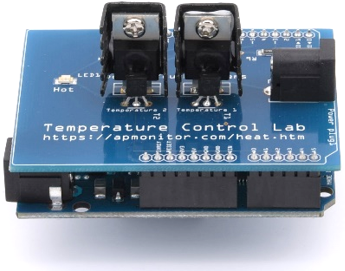
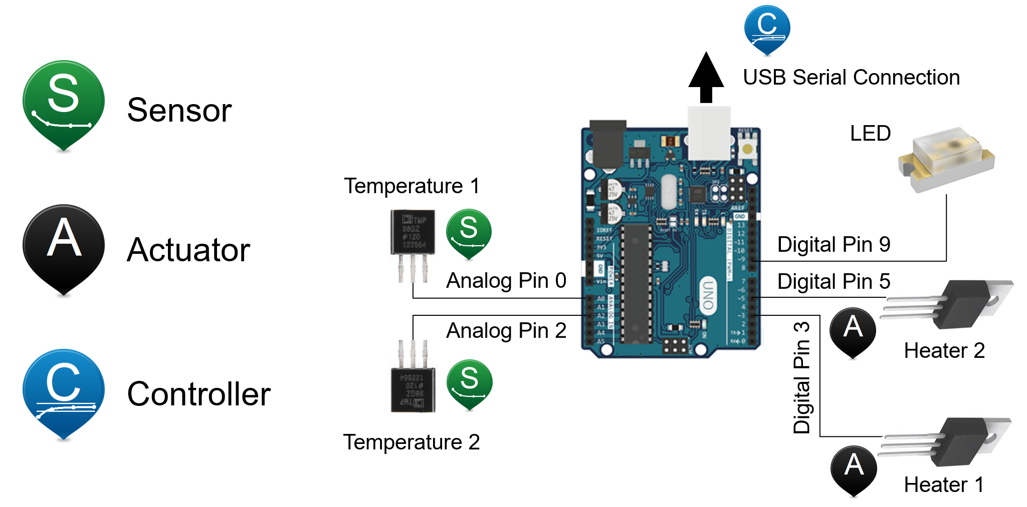
Every control loop has three essential elements including a sensor, actuator, and controller. The TCLab has three actuators (Heater Q1, Heater Q2, and LED), two sensors (Temperature T1, Temperature T1), and a controller that can be built in Python or MATLAB/Simulink through a serial connection to the Arduino.
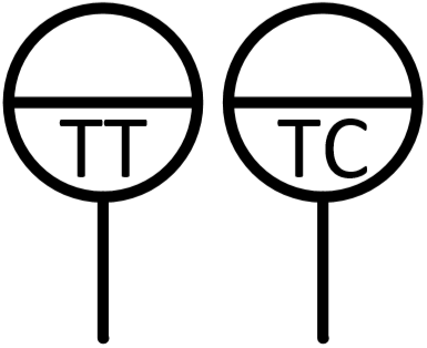
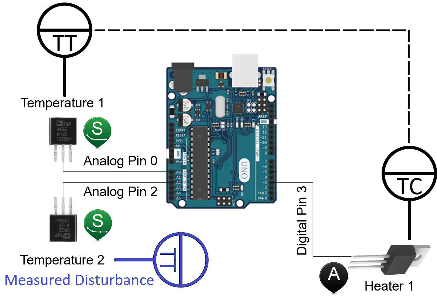
Part I, Process Diagram: Augment the schematic diagram above to indicate the temperature transmitter and temperature controller for a potential control loop where T1 is regulated to a setpoint. Show a potential measured disturbance variable.
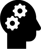
Part II, Block Diagram: Block diagrams show the blocks of a control system. A feedback control system consists of a sensor, actuator and controller that are connected with information flowing in a loop. The loop is created with the sensor providing information to the controller. The controller changes the controller output that then changes the process. The process is measured again and the cycle repeats.
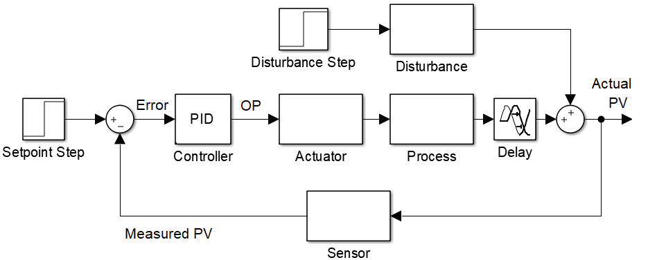
Block diagrams are different than a process diagram in that it is a diagram of the flow of information, not necessarily how the pieces of equipment are physically placed. For the TCLab, fill in descriptions of the blocks and label the signals (lines between the blocks). Include a potential measured or unmeasured disturbance.
Solution
Below is a start to the diagram but without the disturbance information.